
Basic FEA ahead of Pressure vessel, Centrifugal pumps and compressors, wind structures
Dr.Joel Daniel
Compare
₹25000
- Fundamentals of FEA
- Meshing Techniques: Hexa and Tet
- Link Elements applications
- Beam Elements applications.
- Shell element applications
- Solid Element applications
- Best Practices of applying boundary conditions
- Best Practices of applying loading conditions
- Results Interpretation
- Symmetry applications: Cyclic, axisymmetric
- Examples: Centrifugal Pump Casings
- Examples: Propeller shaft
- Examples: Test Rig
- Examples: multistage centrifugal pumps
- Examples: Gear box
- Examples: Spur gears
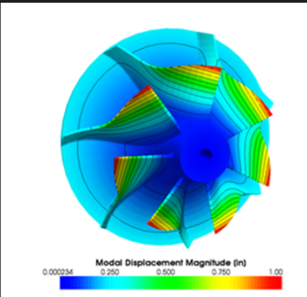
ANSYS Training: Mechanical Vibrations
Dr.Joel Daniel
Compare
₹30000
- Understanding of FEA Basics: ANSYS training in mechanical vibrations typically covers fundamental concepts of FEA, ensuring participants have a solid understanding of how the software works, including meshing, material properties, boundary conditions, and solving techniques
- Modelling Complex Structures: Participants learn how to create accurate 3D models of complex structures and mechanical components relevant to mechanical vibrations analysis using ANSYS
- Meshing Techniques: The training includes meshing strategies and techniques for generating high-quality meshes that capture the geometry and structural features effectively, especially in areas prone to stress concentrations
- Material Modeling: Engineers gain expertise in assigning appropriate material properties and models within ANSYS, considering isotropic or anisotropic behavior, and accounting for damping characteristics relevant to mechanical vibrations
- Boundary Conditions and Loading: Training covers the proper application of boundary conditions and loading scenarios to simulate real-world conditions, ensuring the accuracy of the simulation results
- Modal Analysis: Participants learn how to perform modal analysis using ANSYS, allowing them to extract natural frequencies, mode shapes, and participation factors critical for understanding the vibrational behaviour of structures.
- Harmonic Analysis: Training includes techniques for performing harmonic analysis in ANSYS, enabling engineers to study the response of structures to periodic excitations and identify potential resonance issues
- Transient Analysis: Engineers gain the ability to simulate transient dynamic events, such as start-up, shutdown, or impact loading, to understand the time-dependent response of structures to dynamic forces
- Post-Processing and Result Interpretation: Training covers post-processing tools in ANSYS for interpreting results, visualizing mode shapes, stress distributions, and displacement patterns critical for assessing the vibrational characteristics of structures
- Fatigue Analysis: Participants learn how to perform fatigue analysis within ANSYS, helping them assess the durability and fatigue life of components subjected to cyclic loading
- Optimization Strategies: Training may cover optimization techniques within ANSYS, allowing engineers to iteratively optimize designs to reduce vibrations, improve performance, and meet design criteria
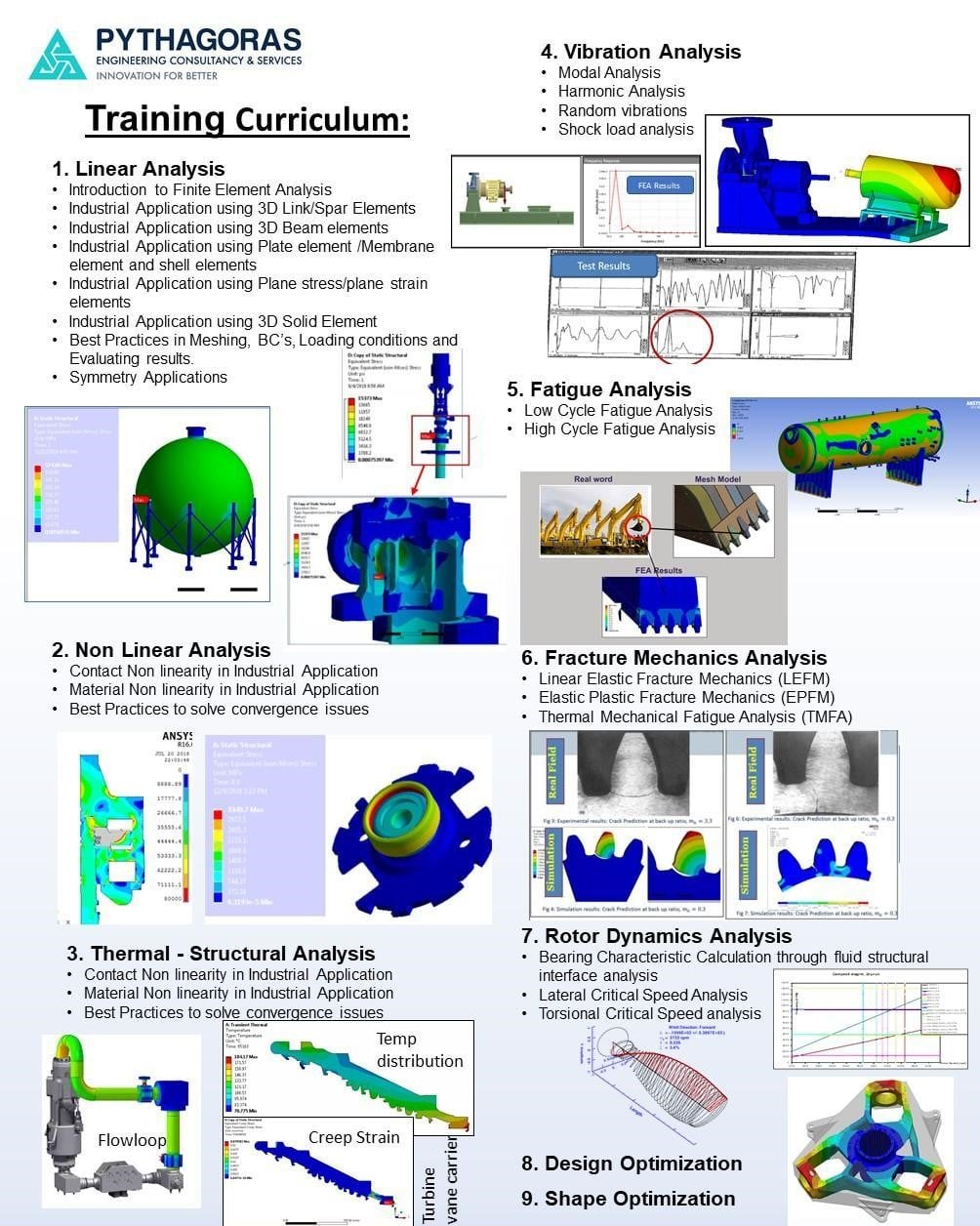
Basic FEA Training for Beginners
Dr.Joel Daniel
Compare
₹20000
- Step 1: Theoretical approach: Students will use theoretical concepts to solve problems. Every one of these classes aids pupils in reviewing the fundamentals and comprehending the issue in depth.
- Step 2:FEA Approach: Students will use FEA to solve the same issue. This part assists students in validating FEA results using manual calculations.
- Step 3: Industrial applications: Industrial applications on similar concepts will be explained in detail. In the third step,
- In the third step, students will be familiar with FEA and the theoretical approach. He will be in a position of handling practical engineering problems
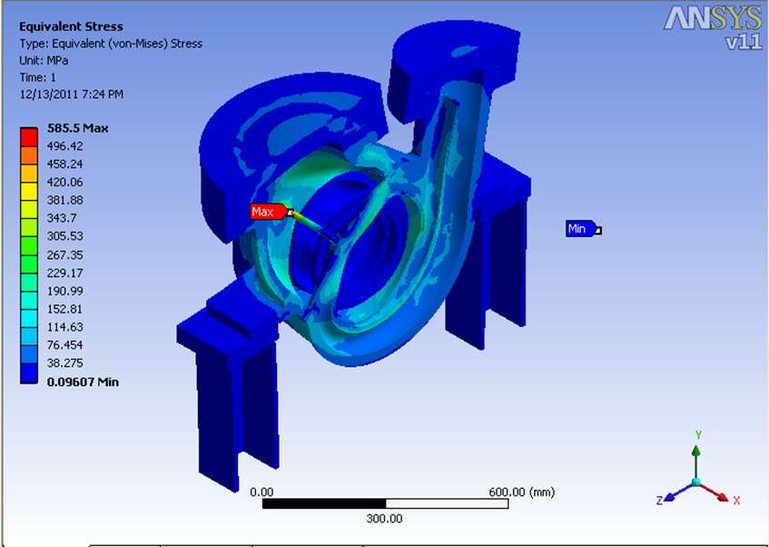
ANSYS Training: Centrifugal pump and Compressor Design and Analysis as per API, Non-API, Euro Code, ASME codes.
Dr.Joel Daniel
Compare
₹20000
- Torsional stiffness for base skid as per HIS standards
- Stress calculations for the base plate under lifting conditions, transportation conditions, wind and seismic load conditions
- Modal analysis assessment of base skid
- Harmonic analysis of the base skid
- Random analysis of the base skid
- Stiffness test acceptance criteria for base skid as per API 610, clause 6.3.7
- Structural assessment of centrifugal pump casing under MAWP and nozzle loads as per API 610 clause 5.3.4
- Leakage assessment of the casings as per API 610 clause 5.3.3
- Calculations of stiffness and damping values for short and long bearings (wear rings, sleeves, and hydraulic bearings)
- Rotor dynamics: Lateral critical speed analysis as per API 610, Annex I.
- Torsional critical speed analysis as per API 610 clause 5.9.2
- Bolt assessment
- Weld assessment as per DNV codes
- Stress analysis for casings and impellers under variable pressure load conditions
- Ultimate Limit State (ULS) for the compressor skid
- Serviceability Limit States (SLS) for the compressor skid
- Accidental Limit States (ALS) for the compressor skid
- Blast Load analysis for the compressor skid.
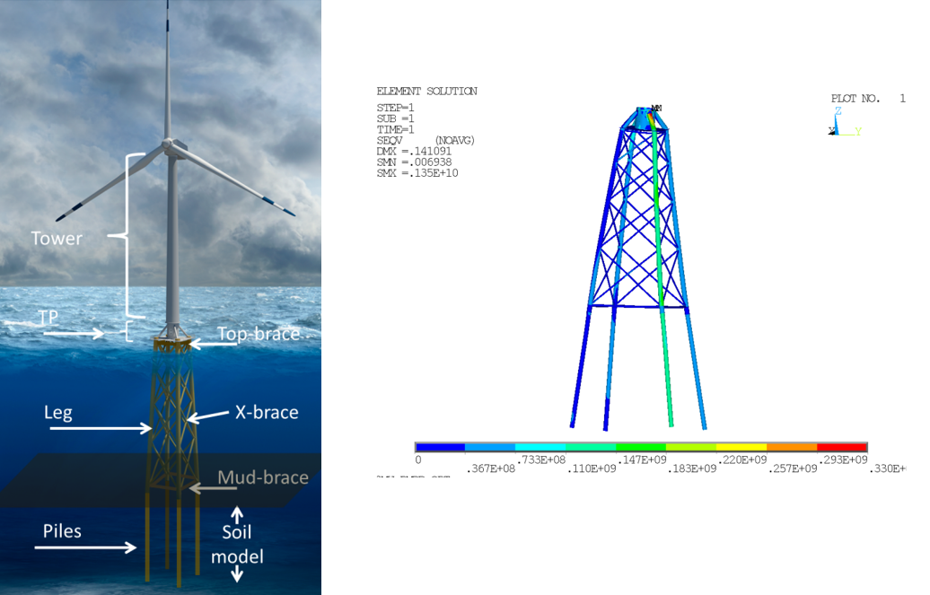
Offshore wind turbine structures
Dr.Joel Daniel
Compare
₹20000
- Participants will have developed a thorough grasp of structural design using FEA, including the use of advanced nonlinear simulations, by the conclusion of this course. They will be prepared to confidently design and assess wind structures, guaranteeing their safety and optimum performance.
- Introduction to Wind Turbine Foundation Structures and DNV Codes
- Introduction to Finite Element Analysis
- Modeling Wind Turbine Foundations for FEA
- Load and Boundary Conditions
- Ultimate Limit State (ULS) Analysis
- Fatigue Limit State (FLS) Analysis
- Serviceability Limit State (SLS) Analysis
- Weld strength Calculations as per DNV codes
- Optimization and Design Review
- Case Studies and Practical Applications
- Real-world case studies of wind turbine foundation projects
- Hands-on exercises in FEA software for ULS, FLS, and SLS analysis
- Practical examples of weld calculations and hotspot analysis
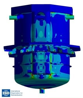
Pressure vessel design using ANSYS software as per ASME
Dr.Joel Daniel
Compare
₹50000
- 1. This course aims to provide a comprehensive understanding of the fundamental concepts and advanced methods involved in the design of pressure vessel structures using Finite Element Analysis (FEA).
- 2. Acquire a comprehensive understanding of solid-shell components in order to effectively develop a finite element analysis (FEA) model for the pressure vessel.
- 3. Acquire the necessary skills to effectively implement the American Society of Mechanical Engineers (ASME) norms and standards in the realm of pressure vessel design.
- 4. To enhance proficiency in doing experiments involving nonlinear materials, contact mechanics, and large deformations, as well as to improve the ability to analyze and comprehend stress-strain relationships.
- 5. This program aims to cultivate and strengthen individuals' critical thinking and problem-solving skills specifically in the context of difficult design issues pertaining to pressure vessel constructions.
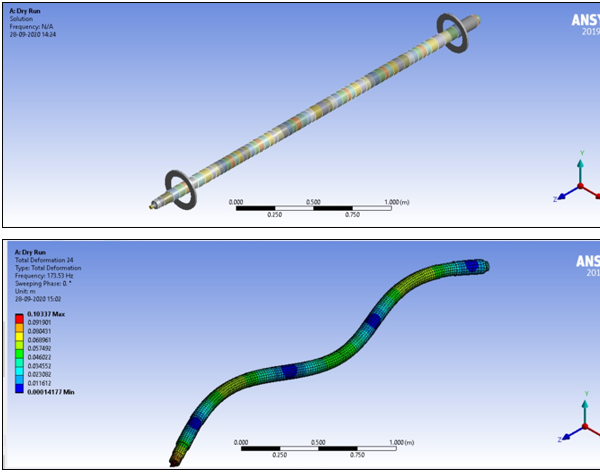
Rotordynamics Analysis
Dr.Joel Daniel
Compare
₹40000
- Carry out the basic end-to-end rotordynamics analysis process in Ansys Mechanical.
- Understand the underlying technical and analysis features that are unique to rotordynamics.
- Describe and apply the essential rotordynamics analysis capabilities: computation of critical speeds, prediction of rotor whirl and system stability, computation of unbalance response, and consideration of start up and shut-down transient responses.
- Results Validation
- Training on Rotor Dynamics tool, ROSS {Open Forum)
- Exercise 1: Lateral critical speed analysis of multi sage centrifugal pump casings
- Exercise 2: Forced response analysis of multi sage centrifugal pump casings
- Exercise 3: Torsional critical speed analysis of multi sage centrifugal pump casings
- Exercise 4: Torsional critical speed analysis of multi sage centrifugal pump casings (VFD)
- Exercise 5: Steady state responce analysis of multi sage centrifugal pump casings (VFD)
- Hydrodynamic Bearing Calculations
- Short bearings (Wear rings, seals, sleeves) calculations
- Gyroscopic Effects
- Rotor Mounted on Bearings
- Design Optimization using DesignXplorer
Advanced Finite Element Analysis using ANSYS Workbench and APDL
Dr.Joel Daniel
Compare
₹100000
- Upon completion of the course, participants will acquire the necessary skills to proficiently use the ANSYS software in addressing both static and dynamic engineering issues, particularly those including thermal coupling.
- Understanding of FEA Basics: ANSYS training in mechanical vibrations typically covers fundamental concepts of FEA, ensuring participants have a solid understanding of how the software works, including meshing, material properties, boundary conditions, and solving techniques
- Modelling Complex Structures: Participants learn how to create accurate 3D models of complex structures and mechanical components relevant to mechanical vibrations analysis using ANSYS
- Meshing Techniques: The training includes meshing strategies and techniques for generating high-quality meshes that capture the geometry and structural features effectively, especially in areas prone to stress concentrations
- Material Modeling: Engineers gain expertise in assigning appropriate material properties and models within ANSYS, considering isotropic or anisotropic behaviour, and accounting for damping characteristics relevant to mechanical vibrations
- Boundary Conditions and Loading: Training covers the proper application of boundary conditions and loading scenarios to simulate real-world conditions, ensuring the accuracy of the simulation results
- Basic FEA: Introduction of FEA,Thermal-structural Analysis,Symmetry Applications FEA Guidelines,3D Solid Element,Plane stress/plane strain elements, Plate element /Membrane element and shell elements,3D Beam elements 3D Link/Spar Elements, Vibration Analysis
- Non-Linear Analysis: Overview of Non-linear analysis, Non-Linear Analysis Procedure in ANSYS, Factors influencing the problem's convergence: Contact Settings, Guidelines for obtaining contact convergence, Case Studies to demonstrate convergence issue and resolve it, exercises on Material Nonlinear Analysis, exercises on Material and Contact Nonlinear Analysis, exercises on Large Deformation Nonlinear analysis, Workshop on Contact Non-linearity analysis
- Vibration Analysis: Introduction to Mechanical Vibrations, Free Vibrations. Single-Degree-of-Freedom (SDOF) and Multi-Degree-of-Freedom (MDOF) Systems , Numerical approach and ANSYS approach to solve the problems, HARMONICALL Y EXCITED VIBRATION, TRANSIENT VIBRATIONS, Modal Analysis using ANSYS, Prestress Modal analysis, Scaled model analysis, Random Vibrations, Harmonic Analysis Using ANSYS, Impact Analysis or shock load analysis
- Rotor Dynamics: rotor dynamics overview,gyroscopic effects,rotor mounted on bearings,simple rotor systems,theory of bearing characteristics calculations, fea approach (ansys and ross) to find the bearing characteristics (stiffness and damping),instability in rotor systems,theoretical approach of finding lateral critical speeds,forced response analysis (unbalance response analysis),fea simulation of lateral critical speed analysis using ansys and ross,fea simulation of lateral critical speed analysis uisng ansys and ross,theoretical approach of finding torsional vibrations,fea simulation of torsional critical speed analysis using ansys and ross,fatigue life calculations in ansys,exercise on stiffness and damping values for long bearings and short bearings using ansys and ross,exercise on lateral analysis study of the multistage centrifugal pump using ansys and ross, exercise on torsional analysis of the pump-motor and direct coupling in ansys,exercise on torsional analysis of the pump-motor and flexible coupling-gear box in ansys,exercise on field fix of boiler feed pump -lateral and torsional analysis
- Offshore wind turbine structures: Introduction to Wind Turbine Foundation Structures and DNV Codes, Foundation Design and Loads, Weld Modeling in FEA, Ultimate Limit State (ULS) Analysis for Welded Joints, Serviceability Limit State (SLS) Analysis for Welded Joints, Accidental Limit States and Load Cases, Fatigue Damage Calculations for Welded Joints, Reporting and Documentation for Weld Analysis, Case Studies and Practical Applications
- Centrifugal Pump and Compressors: Torsional stiffness for base skid as per HIS standards, Stress calculations for the base plate under lifting conditions-transportation conditions- wind and seismic load conditions,Modal analysis assessment of base skid,Harmonic analysis of the base skid,Random analysis of the base skid,Stiffness test acceptance criteria for base skid as per API 610, clause 6.3.7,Structural assessment of centrifugal pump casing under MAWP and nozzle loads as per API 610 clause 5.3.4,Leakage assessment of the casings as per API 610 clause 5.3.3,Calculations of stiffness and damping values for short and long bearings (wear rings, sleeves, and hydraulic bearings),Rotor dynamics: Lateral critical speed analysis as per API 610- Annex I,Torsional critical speed analysis as per API 610 clause 5.9.2,Bolt assessment,Weld assessment as per DNV codes,Stress analysis for casings and impellers under variable pressure load conditions,Ultimate Limit State (ULS) for the compressor skid,Serviceability Limit States (SLS) for the compressor skid,Accidental Limit States (ALS) for the compressor skid, Blast Load analysis for the compressor skid ,Wind and Seismic Load Analysis,
- Pressure Vessel Design: Plastic collapse protection using the elastic stress approach, in accordance with the guidelines outlined in ASME VIII Div. 2,Protection against Plastic Collapse-Global Criteria: Limit Load Analysis,Plastic collapse protection using the elastic-plastic approach, in accordance with the guidelines outlined in ASME VIII Div. 2,Protection against Plastic Collapse-Local Criteria: Elastic Analysis-Triaxial stress Limit,Protection against Plastic Collapse-Local Criteria: Elastic Plastic Analysis-Local strain Limit,Protection against collapse from buckling using elastic , elastic-plastic analysis approach (as per ASME VIII Div.2),Fatigue Life Estimation of Pressure Vessel as per ASME Section VIII Div 2, Lifting Lug strength assessment,Weld assessment,Bolt strength assessment, Thermal ratcheting analysis for pressure vessel as per ASME,Creep assessment for pressure vessel for high temperature applications, Practice Exercises, Lifting Lug strength assessment
- High Cycle Fatigue in FEA Simulation: Introduction to Fatigue, Stress-Life Curves, Mean Stress Effects on S-N Behavior, and Factors affecting S-N Behavior, S-N curve representation and approximations, S-N approach for Notched Members, Example of life estimation using the S-N approach,Workshop1: HCF calculations for Gas turbine components,Workshop2:HCF calculations for automobile components
- Low cycle Fatigue Simulation in FEA Simulation: Introduction to LCF, Strain-Life Curves, Mean Stress Effects on strain-life Behavior, and Factors affecting strain-life Behavior, Strain-Based approach to life estimation, Strain-life approach for Notched Members, Finding stresses in plastic region using Nuber’s rule, Strain energy density or glinka’s rule, Workshop3: LCF calculations for Gas turbine components
- Fatigue from Variable Amplitude Loading in FEA Simulation, Spectrum loads and cumulative damage,Damage quantification, damage fraction, and accumulation,Load interaction and sequence effects,Cycle counting methods; rain flow, and other cycle counting methods,Life estimation using the stress-life approach,Life estimation using a strain-life approach,Crack growth and life estimation models, Workshop 4: LCF and HCF calculations for Gas turbine components
- Fracture Mechanics:Mechanisms of Fatigue and Creep Fatigue,Fundamentals of LEFM and applications to Fatigue Crack Growth Contribution,FRACTURE TOUGHNESS - Kc , KIc,Crack Tip Plastic Zone,Fatigue crack growth,Mean stress effect,Cyclic Plastic Zone Size,Crack Closure,Small Fatigue Cracks and LEFM Assumption,Plastic Extension of LEFM and Elastic Plastic Fracture Mechanics,Applications of Fracture Mechanics to crack growth at notches,SIF for residual stresses,Crack growth and life estimation for variable amplitude loading,Crack growth and life estimation for multiaxial stresses,Fatigue crack growth of weldments ( Constant amplitude Fatigue) Environmental effects: Fatigue crack growth behavior, Corrosion Fatigue, Fretting Fatigue, Low temperature Fatigue, High temperature Fatigue
- Exercises of Fracture Mechanics: Computation of SIF for solid cylinder block through (Elliptical Crack,Pre meshed crack,Arbitrary crack),Crack Propagation simulation for three-point bend specimen (LEFM),Plasticity accountability through LEFM –Spur gear example through perturbation approach,Crack Propagation due to High cycle Fatigue for turbine blade.
- Workshops on Fracture Mechanics :3D Fracture Mechanics Simulation Procedure through ANSYS Workbench (Elliptical Crack- pressure vessel with internal pressure,Pre meshed crack – Rail track from publication,Arbitrary crack- Spur gear root fillet ),Crack Propagation simulation in ANSYS Workbench,LEFM (Linear Elastic Fracture Mechanics)- Spur gear tooth ( ASME publication),LEPM (Linear elastic-plastic Fracture Mechanics)- Gas turbine blade,Thermal Mechanical Fatigue (TMF)- Gas turbine blade, Crack Propagation due to High cycle Fatigue - Gas turbine blade.
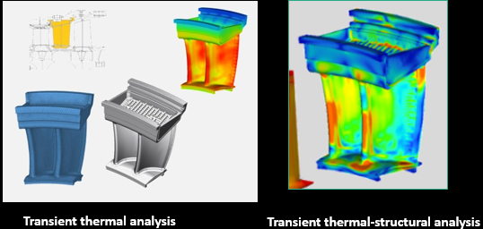
- Steady-state thermal-structural analysis of Gas turbine components: Need of steady-state thermal structural analysis, Preparation of FEA model for thermal analysis at steady state point,Preparation structural FEA for stress calculations at steady state point, Results evaluation, Failure criteria as per ASME
- Transient thermal-structural analysis of Gas turbine components: Need of steady-state thermal structural analysis,Preparation of FEA model for thermal analysis at steady state point,Preparation structural FEA for stress calculations at steady state point, Results evaluation
- Thermal Mechanical Fatigue Assessment of Gas Turbine Components: Theoretical concept of CREEP, Method of finding CREEP Coefficients through strain hardening approach, Performing transient thermal-structural analysis by considering CREEP, Evaluation of the CREEP rupture and creep strength as per Stress approach,Evaluation of the CREEP rupture and creep strength as per Strain approach
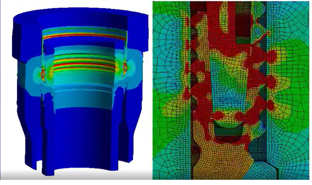
ANSYS Training: Non-Linear Analysis
Dr.Joel Daniel
Compare
₹20000
- What is the concept of nonlinearity and where may we see its application in real-time engineering applications
- The issue of convergence in the non-linear problem
- What are the different kinds of nonlinearity in finite element analysis
- Factors Influencing Convergence Difficulties
- Best Practices for Contact Modelling
- 10 different case studies to help resolve the convergences
- 6 Exercises: Applications of nonlinear analysis in the real world, focusing on subsea drilling, Matine structures, automobiles, and gas turbines
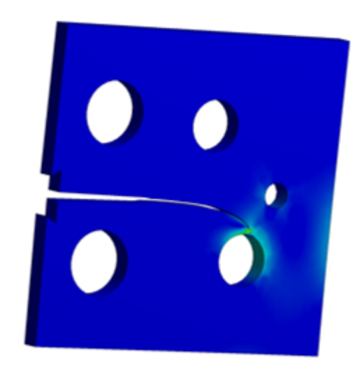
ANSYS Training: Fatigue and Fracture Mechanics
Dr.Joel Daniel
Compare
₹20000
- High Cycle Fatigue in FEA Simulation: Introduction to Fatigue,Stress-Life Curves,Mean Stress Effects on S-N Behavior, and Factors effecting S-N Behavior,S-N curve representation and approximations,S-N approach for Notched Members,Example of life estimation using the S-N approach,Workshop1: HCF calculations for Gas turbine components,Workshop2:HCF calculations for automobile components
- Low cycle Fatigue Simulation in FEA Simulation: Introduction to LCF,Strain-Life Curves,Mean Stress Effects on strain-life Behavior, and Factors effecting strain-life Behavior,Strain-Based approach to life estimation,Strain-life approach for Notched Members,Finding stresses in plastic region using Nuber’s rule , Strain energy density or glinka’s rule ,Workshop3: LCF calculations for Gas turbine components
- Fatigue from Variable Amplitude Loading in FEA Simulation,Spectrum loads and cumulative damage,Damage quantification, damage fraction, and accumulation,Load interaction and sequence effects,Cycle counting methods; rain flow, and other cycle counting methods,Life estimation using the stress-life approach,Life estimation using a strain-life approach,Crack growth and life estimation models, Workshop 4: LCF and HCF calculations for Gas turbine components
- Fracture Mechanics:Mechanisms of Fatigue and Creep Fatigue,Fundamentals of LEFM and applications to Fatigue Crack Growth Contribution,FRACTURE TOUGHNESS - Kc , KIc,Crack Tip Plastic Zone,Fatigue crack growth,Mean stress effect,Cyclic Plastic Zone Size,Crack Closure,Small Fatigue Cracks and LEFM Assumption,Plastic Extension of LEFM and Elastic Plastic Fracture Mechanics,Applications of Fracture Mechanics to crack growth at notches,SIF for residual stresses,Crack growth and life estimation for variable amplitude loading,Crack growth and life estimation for multiaxial stresses,Fatigue crack growth of weldments ( Constant amplitude Fatigue)
- Environmental effects: Fatigue crack growth behavior,Corrosion Fatigue,Fretting Fatigue,Low temperature Fatigue,High temperature Fatigue
- Exercises of Fracture Mechanics: Computation of SIF for solid cylinder block through (Elliptical Crack,Pre meshed crack,Arbitrary crack),Crack Propagation simulation for three-point bend specimen (LEFM),Plasticity accountability through LEFM –Spur gear example through perturbation approach,Crack Propagation due to High cycle Fatigue for turbine blade.
- Workshops on Fracture Mechanics :3D Fracture Mechanics Simulation Procedure through ANSYS Workbench (Elliptical Crack- pressure vessel with internal pressure,Pre meshed crack – Rail track from publication,Arbitrary crack- Spur gear root fillet ),Crack Propagation simulation in ANSYS Workbench,LEFM (Linear Elastic Fracture Mechanics)- Spur gear tooth ( ASME publication),LEPM (Linear elastic-plastic Fracture Mechanics)- Gas turbine blade,Thermal Mechanical Fatigue (TMF)- Gas turbine blade,Crack Propagation due to High cycle Fatigue - Gas turbine blade.


Write a public review